Table of Contents >> Show >> Hide
- Before You Test Anything, Do These Three Things
- Method 1: Test the Transistor with Diode Mode
- Method 2: Test the Transistor with Resistance Mode
- Method 3: Test the Transistor In-Circuit with Voltage Measurements
- Method 4: Use a Dedicated Transistor Tester, hFE Socket, or Curve Tracer
- Common Mistakes When Testing a Transistor
- Which Transistor Test Method Is Best?
- Workbench Lessons and Real-World Testing Experiences
- Conclusion
Transistors are tiny, tireless workers. They switch, amplify, regulate, and generally keep modern electronics from becoming expensive paperweights. But when a circuit starts acting weird, the transistor is often one of the first suspects. The good news is that you do not need a space-age lab to figure out whether one is healthy. In many cases, a digital multimeter, a little patience, and a basic understanding of what the device is supposed to do are enough.
This guide walks through four practical ways to test a transistor, from quick bench checks to more advanced diagnostic methods. We will focus mostly on bipolar junction transistors (BJTs), because they are the easiest to explain and the most straightforward to test with a meter. Along the way, we will also point out where MOSFETs, JFETs, and other transistor types play by slightly different rules. Think of it as transistor detective work, minus the trench coat.
Before You Test Anything, Do These Three Things
1. Identify the transistor type
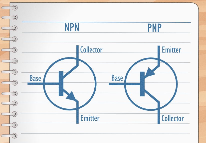
A transistor is not just a transistor. It may be an NPN, PNP, MOSFET, JFET, Darlington pair, or a power device with behavior that differs from a basic small-signal part. If you have the part number, check the datasheet first. That saves time and prevents the classic mistake of testing the right part with the wrong expectations.
2. Know the pinout
Do not trust your memory, and do not trust a random pin order from another transistor that “looks the same.” On a BJT, the terminals are collector, base, and emitter. On a FET, they are usually drain, gate, and source. Getting the pins wrong can make a healthy transistor look suspiciously guilty.
3. Start safe
If you are using diode mode or resistance mode, power the circuit off and discharge any capacitors first. Testing a live circuit in ohms mode is a great way to get nonsense readings and a bad day. If you do move on to live in-circuit voltage testing, work carefully and only when you understand where the energy is coming from and where it can go.
Method 1: Test the Transistor with Diode Mode
If you only learn one technique, make it this one. Diode mode is the fastest and most reliable basic test for a BJT because a bipolar transistor behaves a lot like two PN junctions sharing a base. In other words, it is basically two diodes wearing a trench coat and pretending to be more mysterious than it really is.
How diode mode works
A multimeter in diode mode applies a small test current and measures the voltage drop across a semiconductor junction. A healthy silicon junction usually shows a forward drop in the neighborhood of about 0.5 V to 0.8 V, while reverse bias should read open, OL, or something clearly non-conductive.
How to test an NPN transistor
Set your multimeter to diode mode and remove the transistor from the circuit if possible. Then:
Base to emitter: Place the red probe on the base and the black probe on the emitter. A healthy NPN transistor usually shows a forward voltage drop.
Base to collector: Keep the red probe on the base and move the black probe to the collector. You should see a similar forward drop.
Reverse both tests: Swap the probes for each junction. The meter should now indicate open circuit or OL.
Collector to emitter: Measure between collector and emitter in both directions. In a basic BJT, you generally should not see a normal diode-like forward reading here. A dead short is bad news.
How to test a PNP transistor
Same logic, opposite polarity. Put the black probe on the base and use the red probe on the emitter and collector in turn. Good junctions should conduct one way and block the other.
What the readings usually mean
If both base junctions conduct in the forward direction and block in reverse, the transistor is probably okay at a basic level. If a junction reads shorted both ways, the transistor is likely damaged. If it reads open both ways where you expected conduction, the junction may be blown open. If collector-to-emitter looks shorted in both directions, that is usually a big red flag.
Best use case
Use diode mode when you want a quick go/no-go transistor test for a BJT on the bench. It is fast, clear, and much more useful than guessing based on how confident the transistor looks.
Method 2: Test the Transistor with Resistance Mode
This is the old-school approach. It still works, although it is usually less precise than diode mode on a modern digital meter. Think of resistance mode as the transistor test your multimeter’s grandparent would approve of.
Why resistance mode can help
Because a BJT contains PN junctions, a meter set to ohms can sometimes show you that current flows more easily in one direction than the other across the base-emitter and base-collector paths. That directional difference helps you spot whether the junctions are behaving normally.
How to do it
With power removed and the transistor ideally out of circuit, measure:
Base to emitter in both probe directions
Base to collector in both probe directions
Collector to emitter in both probe directions
On a good transistor, the base junctions should not behave like a simple wire. You should see a noticeable difference between one probe orientation and the other. Collector-to-emitter also should not read as a direct short in a normal small-signal BJT.
Why this method is less popular now
Resistance mode is more sensitive to the multimeter design, the selected range, and whatever other components may still be connected around the transistor. In-circuit readings can become misleading very quickly because nearby resistors, diodes, coils, and semiconductor paths all love to “help.” Unfortunately, their help is usually not helpful.
Best use case
Use resistance mode when your meter lacks a good diode test function, when you want a second opinion, or when you are working through a rough troubleshooting process on older equipment. It is not glamorous, but it can still reveal shorts and opens.
Method 3: Test the Transistor In-Circuit with Voltage Measurements
A transistor can pass a bench test and still fail in the actual circuit. That is why live in-circuit voltage testing matters. This method tells you whether the transistor is being driven correctly and whether it is responding the way the circuit expects.
Why live testing matters
A transistor is not just a component. It is a role player. It might be acting as a switch, an amplifier, a current regulator, or part of a feedback loop. Voltage testing shows whether the transistor is doing its job under real operating conditions.
Example: Testing an NPN transistor used as a low-side switch
Imagine a common setup where the emitter is tied to ground, the collector goes to a load, and the load then connects to the supply voltage.
When the transistor is off, the base-emitter voltage is usually too low to turn it on, and the collector may sit near the supply through the load.
When the transistor is on, the base-emitter junction of a silicon BJT often measures roughly 0.6 V to 0.8 V. If the transistor is driven hard into saturation, the collector-emitter voltage usually falls low relative to the supply.
What faults look like
If the base is being driven properly but the collector never changes state, the transistor may be open, damaged, miswired, or connected to a failed load. If collector and emitter stay nearly shorted regardless of drive, the transistor may be shorted. If the voltages look almost right but the circuit is unstable, the problem could be thermal, intermittent, or upstream in the bias network.
What about PNPs and MOSFETs?
PNP transistors reverse the polarity logic, and MOSFETs are different again because the gate is insulated and the device is voltage-driven, not current-driven like a BJT. A MOSFET may look fine in a simple continuity check yet still misbehave because of threshold issues, gate damage, or dynamic switching problems. That is why it is important not to force BJT expectations onto every three-legged component you meet.
Best use case
Use in-circuit voltage testing when the transistor passes bench checks but the device, board, or product still is not working. This method is especially useful in switch-mode circuits, relay drivers, LED drivers, and audio stages.
Method 4: Use a Dedicated Transistor Tester, hFE Socket, or Curve Tracer
Sometimes you want more than a simple pass/fail. You want pin identification, gain, leakage clues, switching behavior, or full device characterization. That is where dedicated tools step in.
Option A: Multimeter transistor socket or component tester
Some multimeters include a small hFE transistor test socket. You plug the transistor into the labeled holes for emitter, base, and collector, and the meter gives you a gain reading. This can be handy for checking whether the transistor is alive and whether its terminals are arranged as expected.
Standalone component testers go even further. Many can identify transistor type, pinout, gain, and sometimes approximate leakage or threshold behavior. For quick sorting on a workbench, these tools are wonderful. They are like having a tiny customs officer for semiconductors.
Option B: Oscilloscope testing
An oscilloscope helps when the transistor operates in a switching or amplifying circuit and timing matters. You can watch the waveform at the base or gate, compare it with the collector or drain waveform, and see whether the transistor is switching cleanly, saturating too slowly, distorting, ringing, or refusing to turn off when politely asked.
Option C: Curve tracer or source-measure unit
This is the advanced route. A curve tracer or source-measure unit (SMU) lets you characterize the transistor by sweeping voltages and currents and plotting its behavior. This is how engineers evaluate things like gain regions, threshold behavior, leakage, breakdown trends, and matching between parts. It is more than troubleshooting. It is the transistor version of a full medical exam.
Best use case
Use dedicated testers and advanced instruments when you need more than “good” or “bad.” They are especially useful for matching transistors, diagnosing intermittent failures, evaluating power devices, or confirming whether a suspect part still meets its design expectations.
Common Mistakes When Testing a Transistor
Testing in-circuit too early
Parallel paths can fool your meter. If the reading makes no sense, lift one leg or remove the transistor before declaring victory or disaster.
Ignoring the datasheet
Many transistor failures are actually testing mistakes caused by wrong pin identification or wrong expectations for a specific part type.
Assuming “not shorted” means “good”
A transistor can fail under load, at temperature, or at speed while still looking acceptable in a quick static test. That is why advanced testing and in-circuit measurement matter.
Forgetting the surrounding circuit
If a transistor keeps failing, the transistor may not be the root cause. Bad drive signals, missing flyback protection, overloaded outputs, overheating, or faulty bias components can kill the replacement too.
Which Transistor Test Method Is Best?
For most people, the best first step is diode mode. It is quick, accurate enough for basic BJT checks, and easy to interpret. Resistance mode is a useful backup. In-circuit voltage testing is the best method when the transistor behaves differently on the board than on the bench. And dedicated testers or curve-tracing tools are the smartest choice when you need deeper analysis.
In short, the right method depends on the question you are trying to answer. Are you checking whether the transistor is obviously dead? Start with diode mode. Are you trying to understand why a circuit still fails under power? Move to live voltage checks or scope work. Are you comparing devices or validating performance? Bring out the nicer test gear and pretend this was the plan all along.
Workbench Lessons and Real-World Testing Experiences
Anyone who spends enough time testing transistors eventually collects a small museum of avoidable mistakes. One of the most common experiences is finding a transistor that seems dead in circuit, only to discover that the real problem was a resistor, a shorted diode, or a neighboring component creating a false reading path. That is why experienced technicians often trust a suspicious in-circuit reading only halfway. The moment a measurement looks weird, they isolate the part and test again. The second reading usually tells the truth.
Another classic experience is the “perfectly fine transistor that was installed backwards.” This happens more often than people admit. Two devices can share the same package style and still have different pinouts. A technician may replace a bad transistor, power the board, and watch absolutely nothing improve. After a few muttered comments not suitable for a service manual, the datasheet comes out, the pin order gets checked, and suddenly the mystery solves itself. It is a humbling reminder that transistor testing is not just about numbers. It is also about orientation, context, and not getting overconfident because the package looks familiar.
There is also the experience of meeting a transistor that passes a basic diode test but fails under real operating conditions. This is especially common in switching applications and power electronics. On the bench, the junctions look normal. Under load, the part heats up, leaks, saturates poorly, or refuses to switch cleanly. That kind of failure teaches an important lesson: a quick multimeter check is valuable, but it is not the final word. If the circuit still misbehaves, live voltage checks and waveform analysis become essential.
Beginners often remember the first time they test a transistor with diode mode and realize the device is much less mysterious than it first seemed. The readings start to form a pattern. Base to emitter conducts one way. Base to collector conducts one way. Reverse the leads and the junction blocks. Suddenly the transistor stops feeling like a black box and starts feeling like a logical device. That moment is useful because it turns troubleshooting from guessing into observation.
Many hobbyists also discover that inexpensive component testers can be surprisingly helpful. A small tester that identifies whether a part is NPN, PNP, or MOSFET and labels the pins can save a huge amount of time. It is not a substitute for understanding the circuit, but it is a great confidence booster when your parts bin has become a mixed family reunion of unlabeled semiconductors.
Perhaps the biggest real-world lesson is that transistor testing gets easier when you stop asking only, “Is this part good?” and start asking, “What should this part be doing right now?” That question changes everything. It leads you to the schematic, the expected voltages, the bias conditions, the load, and the thermal environment. In other words, it pushes you from random probing to actual diagnosis. And once that habit forms, transistor testing becomes less about luck and more about method. The transistor may still fail, of course, but at least now it has to fail on your terms.
Conclusion
Testing a transistor does not have to feel intimidating. With the right method, it becomes a structured process. Start simple with diode mode, use resistance mode when needed, verify behavior with live voltage measurements, and move to dedicated testers, oscilloscopes, or curve tracers when the situation calls for deeper insight. The more clearly you understand the transistor’s job in the circuit, the easier it is to decide whether the part is healthy, weak, misdriven, or simply blamed for someone else’s bad behavior.
And that is really the trick: test the part, test the context, and let the readings tell the story.