Table of Contents >> Show >> Hide
- What Does “A Wrencher On Your Oscilloscope” Mean?
- How Oscilloscope Art Works
- The Gear You Need
- Step-by-Step: How the Wrencher Appears
- Why Audio Can Draw Pictures
- The Practical Electronics Lessons Hidden in the Fun
- Common Problems and Fixes
- Why Makers Love Projects Like This
- Where This Fits in Oscilloscope Culture
- Safety Tips Before You Try It
- Experiences From the Bench: What It Feels Like to Put a Wrencher on a Scope
- Conclusion
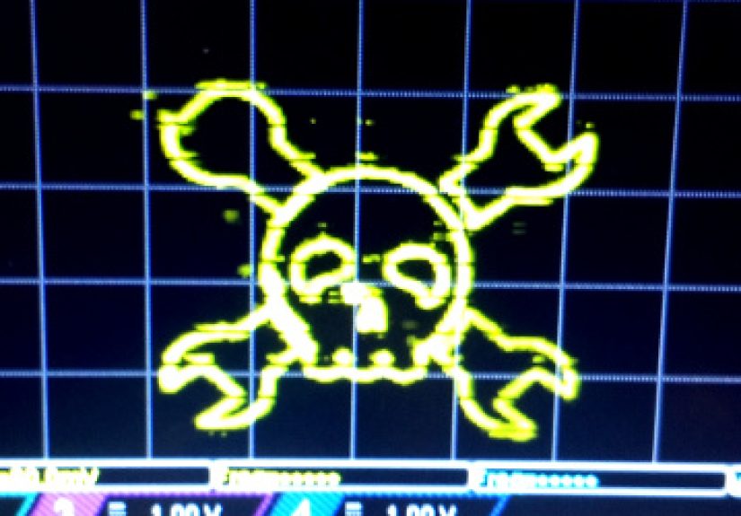
Most people meet an oscilloscope in one of two moods: either it is saving the day during a debugging session, or it is silently judging them from a crowded workbench. But every so often, the humble scope gets promoted from test instrument to art display. That is the spirit behind A Wrencher On Your Oscilloscope, a wonderfully nerdy idea that turns voltage signals into a recognizable image: the Hackaday-style Jolly Wrencher logo glowing on a scope screen.
At first glance, the project sounds like lab folklore. You connect the left and right channels of an audio output to an oscilloscope, switch the scope into X/Y mode, adjust a few settings, and suddenly a tool-shaped skull-and-crossbones mascot appears where a waveform should be. It is part electronics lesson, part browser experiment, part “look what I made with wires and stubbornness.”
This article explains what is happening, why it works, what gear you need, and what practical lessons the project teaches about oscilloscopes, signal generation, audio waveforms, vector graphics, and safe measurement habits. Bring your curiosity. Leave the mains wiring alone unless you know exactly what you are doing.
What Does “A Wrencher On Your Oscilloscope” Mean?
The phrase refers to a maker project where an oscilloscope is used as a vector display. Instead of showing voltage over time in the usual way, the scope is placed in X/Y mode. In this mode, one input controls the horizontal position of the electron beam or plotted point, while another input controls the vertical position. Feed the scope the right pair of synchronized signals, and the dot traces lines, curves, and shapes.
The “Wrencher” is a nod to the Jolly Wrencher, the familiar wrench-themed emblem associated with hacker and maker culture. The clever twist is that the picture is not drawn by pixels. It is drawn by voltages. The left audio channel can act like the X coordinate, the right audio channel like the Y coordinate, and the oscilloscope becomes a glowing Etch A Sketch that never asks for batteries because it is already plugged into the wall.
How Oscilloscope Art Works
The Standard Oscilloscope View
In normal operation, an oscilloscope displays voltage on the vertical axis and time on the horizontal axis. That is perfect for diagnosing signals: square waves, sine waves, digital pulses, power-supply ripple, sensor outputs, serial buses, ignition events, and all the other electrical gossip a circuit is willing to share.
The vertical controls set voltage sensitivity. The horizontal controls set the time scale. The trigger system stabilizes repeating signals so the waveform does not wander across the screen like a caffeinated worm. Together, these systems let engineers and technicians see what a multimeter cannot: how voltage changes moment by moment.
X/Y Mode Changes the Game
In X/Y mode, the oscilloscope stops using time as the horizontal axis. Instead, channel one typically drives the X position and channel two drives the Y position. When the two signals are related, the screen can display Lissajous figures, phase relationships, frequency ratios, circles, ellipses, spirals, and more complex drawings.
That is the secret sauce behind oscilloscope art. A stereo audio signal already contains two synchronized channels. If the left channel carries one coordinate stream and the right channel carries another, the scope can plot a moving dot through space. Make those coordinates trace a logo, and the screen draws the logo. Make them dance in time with music, and you get oscilloscope music: part math, part synthesizer, part electric campfire.
The Gear You Need
You do not need a laboratory that looks like a NASA basement. A basic setup may include:
- An oscilloscope with X/Y mode
- A computer, phone, Raspberry Pi, or audio interface capable of stereo output
- A stereo cable split into left and right channels
- Two oscilloscope probes or BNC input connections
- A known-good audio file, browser demo, or signal generator script
- Patience, because the first attempt may look less like a wrencher and more like a stunned jellyfish
Analog CRT oscilloscopes are especially charming for this because they draw with a bright moving beam and natural persistence. Digital oscilloscopes can work too, though their display behavior, sample density, memory depth, and refresh style may affect how smooth the image looks. Some digital scopes offer excellent X/Y displays; others act like they were invited to an art party and brought a spreadsheet.
Step-by-Step: How the Wrencher Appears
1. Put the Oscilloscope in X/Y Mode
Find the display or acquisition menu and select X/Y mode. On many scopes, channel one becomes X and channel two becomes Y. If your scope labels it differently, trust the manual over your optimism.
2. Connect Stereo Audio to the Scope Inputs
Split the audio output so the left channel goes to one oscilloscope input and the right channel goes to the other. Keep signal levels modest. Audio outputs are not power amplifiers, and oscilloscope inputs are measurement ports, not snack trays for random voltage.
3. Start the Generated Signal
A browser-based generator, a WAV file, or a small program can produce the two-channel signal. The signal contains the X and Y coordinate information that tells the scope where to move the dot. When the stream is ordered correctly, the dot sweeps through the points needed to sketch the Wrencher.
4. Adjust Volts Per Division
If the image is too tiny, increase the sensitivity. If it is running off the screen like it owes money, reduce the sensitivity. You are scaling the horizontal and vertical deflection until the graphic fits neatly in the display area.
5. Adjust Timebase, Persistence, and Intensity
Some scopes need a longer timebase, display persistence, or memory depth adjustment to show the full figure clearly. On a CRT, beam intensity and focus matter. On a digital scope, persistence mode can help the image accumulate instead of flickering into abstract modern art.
Why Audio Can Draw Pictures
Audio is simply voltage changing over time. A stereo audio file has two related voltage streams. When those streams are sent to speakers, they move air. When they are sent to an oscilloscope in X/Y mode, they move a dot.
Imagine a drawing made from thousands of points. Each point has an X coordinate and a Y coordinate. If a program converts those coordinates into two audio waveforms, the left channel can carry X values and the right channel can carry Y values. The oscilloscope does not know it is drawing a logo. It only knows that one voltage says “move sideways” and the other says “move up or down.”
This is similar to vector graphics, where images are described by paths rather than rows of pixels. Old arcade machines, laser projectors, and certain display systems used related ideas. The oscilloscope version feels magical because a tool designed for measurement suddenly becomes a display for geometry, timing, and creativity.
The Practical Electronics Lessons Hidden in the Fun
Bandwidth Still Matters
Oscilloscope bandwidth affects how accurately fast-changing signals are displayed. A low-bandwidth scope may soften edges or distort fine details. For a simple audio-driven drawing, the frequencies are often within a comfortable range for many scopes, but the lesson remains useful: your instrument must be fast enough for the signal you want to see.
Sample Rate Matters on Digital Scopes
Digital oscilloscopes sample analog signals and reconstruct them on screen. If the sample rate is too low, the display may miss detail or produce aliasing. That is why oscilloscope selection guides often emphasize the relationship between sample rate, bandwidth, and the signal under test. In art mode, poor sampling can turn smooth lines into dots, gaps, or odd shapes.
Probes Are Not Just Pointy Wires
A standard 10X passive probe reduces circuit loading and usually offers better high-frequency behavior than a 1X setting. Probe compensation also matters. If a probe is not compensated properly, square waves can look rounded, peaked, or distorted. In a normal repair job, that can lead to wrong conclusions. In oscilloscope art, it can make your Wrencher look like it skipped leg day.
Grounding Is Not Optional
Oscilloscope grounding deserves respect. Many bench oscilloscopes connect the probe ground clip to earth ground. That is safe and normal when used correctly, but dangerous if you clip it to the wrong point in a live circuit. For this audio-art project, stick to low-voltage, isolated audio outputs and avoid connecting the scope to hazardous mains-powered circuits unless you have the proper training, probes, and isolation equipment.
Common Problems and Fixes
The Image Is Diagonal
A diagonal line often means both channels are receiving the same signal, or the audio source is outputting mono instead of stereo. Check that the left and right channels are separate. Some adapters, phone settings, browser permissions, or operating-system audio effects can collapse stereo into mono.
The Image Is Upside Down or Backward
Swap channels or invert one channel on the scope. Vector drawings are sensitive to orientation. A reversed axis can transform a proud Wrencher into its mirror-universe cousin.
The Image Is Too Dim
Increase intensity on a CRT scope or enable display persistence on a digital model. You can also adjust signal amplitude, but avoid overdriving the scope input or the audio output. More voltage is not always more better, despite what every impatient troubleshooter has whispered at midnight.
The Image Flickers
Flicker may come from low refresh speed, short persistence, weak signal levels, or digital display limitations. Try changing memory depth, persistence, sample rate, or playback volume. If the source is a browser demo, close unnecessary tabs. Yes, even the one with 47 unread shopping carts.
Why Makers Love Projects Like This
The charm of A Wrencher On Your Oscilloscope is not only that it works. It is that it teaches several serious concepts through play. You learn about X/Y plotting, stereo signals, parametric curves, voltage scaling, display persistence, grounding, signal paths, and probe behavior without sitting through a lecture that smells faintly of dry markers.
For electronics beginners, the project makes oscilloscopes less intimidating. Instead of being a mysterious box with knobs, the scope becomes interactive. Turn a control and the image changes. Swap a channel and the picture flips. Adjust scaling and the logo grows. It is immediate, visual feedback, which is one of the best ways to learn.
For experienced engineers, it is a reminder that instruments are not just tools for compliance reports and bug hunts. They can be playful. A good bench instrument can diagnose a switching regulator in the morning, display a goofy logo after lunch, and reveal a bad ground connection before dinner. That is range.
Where This Fits in Oscilloscope Culture
Oscilloscope art has a long and delightfully strange history. Lissajous figures have been used for phase and frequency comparisons for decades. Musicians and visual artists later pushed the idea into audiovisual performance, generating images from sound itself. Makers have used scopes to display clocks, games, logos, vector animations, and even surprisingly complex graphics.
The Wrencher project sits comfortably in that tradition. It is not trying to replace a monitor. It is celebrating the fact that a measurement device can become a canvas when you understand the physics behind the display. In a world full of sealed gadgets, this kind of project says, “Open the hood. The weird stuff is where the learning lives.”
Safety Tips Before You Try It
- Use low-voltage audio outputs only.
- Do not connect probe ground clips to unknown live circuits.
- Start with low volume and low input sensitivity.
- Use proper probes, cables, and adapters.
- Read your oscilloscope manual before assuming how X/Y mode is wired.
- Do not float a bench oscilloscope by defeating the safety ground.
- If you are unsure, ask someone experienced before connecting equipment.
The safest version of this project is a simple audio-output-to-scope experiment using isolated, low-voltage signals. Keep it there until you fully understand what the ground reference is doing. Electricity is fun, but it is not impressed by confidence.
Experiences From the Bench: What It Feels Like to Put a Wrencher on a Scope
The first time you try to draw a Wrencher on an oscilloscope, do not expect cinematic perfection. Expect a ritual. You gather cables, dig for adapters, discover one cable is stereo only in spirit, and spend five minutes wondering why your expensive instrument is displaying a diagonal line with the emotional depth of a printer error.
Then comes the first small victory. You switch the audio output to true stereo, or you swap the left and right plugs, and the diagonal line begins to open into a shape. It may not be the Wrencher yet. It may look like a wrench that has had a difficult commute. But it is clearly no longer random noise. That moment is addictive because it proves the concept: the scope is listening to the two channels as coordinates.
Next, you start adjusting the scale. One channel is too tall, so the logo stretches vertically like a funhouse reflection. The other channel is too small, so the image becomes a thin little ghost in the center of the screen. With each knob turn, the drawing becomes more recognizable. You are not editing an image file; you are shaping voltage space. That feels different. It feels physical.
Persistence is another lesson that arrives quickly. On a digital scope, the display may appear dotted or incomplete until you increase persistence or adjust acquisition settings. On an analog scope, intensity and focus become part of the artwork. Too dim, and the Wrencher disappears. Too bright, and the lines bloom into a fuzzy neon cloud. Somewhere in between is the sweet spot where the logo looks crisp enough to photograph and strange enough to feel like a secret handshake.
One of the best experiences is showing it to someone who has only seen oscilloscopes used for repair. They expect a waveform. Instead, they see a logo. The first reaction is usually confusion, followed by a grin, followed by the question every maker loves: “Wait, how is it doing that?” That question opens the door to X/Y mode, stereo audio, parametric plotting, and the idea that signals can represent more than sound or sensor data.
The project also makes you a better troubleshooter. You become more aware of channel matching, gain differences, grounding, connector quality, sampling behavior, and the way small setup choices affect what appears on the display. A loose adapter can distort the drawing. A mono output can erase half the concept. A scope setting buried three menus deep can make the difference between “beautiful vector logo” and “electrical spaghetti.”
Most importantly, it gives the bench a little personality. Electronics work can be serious, especially when deadlines, broken boards, or mysterious intermittent failures are involved. A Wrencher on the oscilloscope is a reminder that the same tools used for precision measurement can also be used for curiosity. That balance matters. It keeps learning playful, and playful learning tends to stick.
So yes, the Wrencher is a novelty. But it is a useful novelty. It teaches the behavior of an oscilloscope in a way a textbook diagram cannot. It rewards careful setup. It exposes sloppy assumptions. It makes invisible signals visible, then makes them funny. For a maker, technician, student, or electronics writer, that is a pretty good day at the bench.
Conclusion
A Wrencher On Your Oscilloscope is more than a clever party trick for people who own too many BNC cables. It is a compact lesson in how oscilloscopes think, how audio can become geometry, and how X/Y mode turns voltage into position. The project blends electronics, art, signal theory, and hacker humor into one glowing display.
Whether you are an engineer, mechanic, hobbyist, student, or curious web reader, this project offers a friendly doorway into deeper oscilloscope knowledge. You learn why bandwidth matters, why stereo separation matters, why probes matter, and why safety grounding should never be treated casually. And at the end of it all, you get a tiny illuminated Wrencher staring back from the screen as if to say, “Congratulations. You have successfully made test equipment weird.”